By John Rogers
A fundamental safety requirement is for drivers to have adequate visibility when approaching the tunnel, at the moment of entry, within the tunnel and when exiting.
To provide adequate visibility, lighting systems are designed to overcome the “black hole” effect at the entry portal during daylight hours. Such lighting is energy intense, requiring up to three hundred kilowatts at each portal that must be adjusted downward as ambient daylight declines approaching nightfall or on overcast and rainy days. The process reverses at dawn.
As the driver enters the tunnel their eyes gradually adapt to the lower lighting level which can be progressively reduced until a lower constant lighting level can be applied in a long tunnel. This progressive lighting reduction for visual adaptation is a function of stopping distance and time so the design speed for the tunnel and the entry road gradient dictates the distance over which the portal boost lighting is installed.
At the exit, the eye adapts much faster to increasing daylight and boost lighting is provided for the driver to have adequate visibility in their rear-view mirrors.
Tunnel lighting innovations between the 1960s and 1990s
Construction of major tunnel works in Sydney commenced in the late 1960’s. The first, Sydney Domain Tunnel, was designed for illuminance conditions similar to methods applied to interior lighting. Mascot Tunnel followed soon after, also designed for illuminance. Both cut and cover tunnels employed the technology of the time: fluorescent lamps. In that era the only other electric lamp available was the high-pressure mercury vapour lamp. While this lamp emitted white light and provided much higher light output and power, it was totally unsuitable for tunnel lighting safety due to a fifteen minute restrike time in the event of losing a few cycles of power supply. While the low-pressure sodium (LPS) lamp was available, its monochromatic yellow colour was generally considered unsuitable and only one tunnel at the time, in Canberra, incorporated LPS.
By the time the cut and cover Kings Cross Tunnel was built in Sydney in the mid 1970’s, high pressure sodium lamps (HPS) were available as a mature technology. The original tunnel lighting, also designed on an illuminance basis by Department of Main Roads (DMR) NSW, was the first to incorporate high levels of boost lighting at the portals using HPS lamps supplemented by fluorescent lamps for the interior and night lighting systems. The tunnel lighting designer Lloyd Lott, Supervising Electrical Engineer with DMR NSW, employed an innovative lighting design method. In an Australian first, he incorporated international elements of tunnel lighting design including the importance of the brightness of the walls, and that entrance lighting needed to correspond to the varying levels of external daylight.
While the first attempt at an International Standard for Tunnel Lighting was published in 1973, considerable research in Europe and Japan recognised from practical experience that the recommendations, “did not give a satisfactory answer to all problems concerned with tunnel lighting.”
In 1990, the International Commission on Illumination (CIE) published the first comprehensive guide for tunnel lighting. This described the methodology for assessing the visual conditions on the approach to the tunnel as a basis for the quantitative design of the portal lighting; the extent of the transition lighting; as well as the interior, night-time and mains failure lighting. This guide adopted the concept of luminance-based design as opposed to previous illuminance-based practice. Luminance-based design recognises that the human eye sees objects through their intrinsic brightness rather than the amount of light falling on the surface.
A further important contribution of this guide was in the classification of tunnels and the requirements for lighting based on length, traffic mix, visibility of the exit, wall reflectance and traffic volume.
The techniques described in this guide were employed in the Sydney Harbour Tunnel (SHT). This opened in 1992 and was the first “very” long tunnel in Australia (which refers to a tunnel of sufficient length to permit a second interior zone where the lighting can be reduced to the equivalent of night time lighting). A luminance-based design, predicated on the portal surround luminance, quantified the levels of boost and basic lighting applied to both the road surface and tunnel walls. In another Australian first, photometric data for the HPS and fluorescent luminaires, together with reflectance data for all surfaces, were incorporated into a computer program to produce a compliant design that was later verified by measurement. As with all tunnels, competition for available space for services required comprehensive space proofing.
Another SHT innovation was its lighting control system. Earlier tunnels were monitored by photocells measuring the horizontal daylight illuminance (lux) at the portal. However, this was prone to error as daytime shadows evolved around the portal and grime, including bird fouling, affected the readings. SHT initiated monitoring of the 20 degree conic surrounding the portals as luminance values (cd./m.sq.) from a luminance photometer located at the stopping distance from the portal. A 4 to 20 milliampere (mA) signal from the photometer to the control system enabled more responsive and reliable lighting adjusting the portal light levels analogous to the brightness of the portal surrounds as seen by the driver.
During the 1990s, other capital cities were also expanding their road networks, creating road tunnels in Perth, Adelaide, Melbourne and Brisbane. Sydney, however, was moving faster as the orbital expanded.
Evolution of tunnel lighting systems and solutions
Following the SHT example, tunnels in Perth, Brisbane and Sydney proceeded with a continuous end to end fluorescent lamp basic lighting system supplemented by HPS boost lighting near portals. Continuous lighting is recognised as providing a more uniform and visually comfortable system without apparent dashboard flicker. However, the economics of spacing luminaires further apart could not be resisted. Fluorescent lighting systems with linear (long) light sources were permitted in guides and standards, as long as the dark space between the lighting tubes did not exceed the length of the light space. The Eastern Distributor tunnel in Sydney was the first of this generation.
Similarly, these standards allowed point source luminaires to be installed provided they met flicker frequency requirements. HPS lamps at up to 15 metres spacing were adopted for Mullum-Mullum Tunnel, Brisbane’s Clem 7, Airport Link and Legacy Way. Since HPS lamps provided the bulk of exterior road lighting and tunnel entrance lighting, the deployment of HPS lamps, with their characteristic golden white colour, passed without apparent comment. Point source luminaires in road tunnel interiors are now the norm.
Throughout the 2000–2010-decade, LED light sources became a mature technology. Sydney M4 East (a very long) tunnel adopted LEDs for the interior lighting supplemented by HPS portal boost lighting. Sydney North Connex and M8 tunnel followed with a full boost and basic LED lighting system. This solution was then repeated in the recently opened M4-M8 Link Tunnel.
Development of Australian Standard AS/NZ1158.5
An update of CIE 1990 was published in 2004 and a number of Australian tunnels were designed to this guide, however it became apparent that the CIE 2004 guide was inadequate for the range of tunnels and long underpasses.
Drawing on the CIE guide and British tunnel lighting standards, and now with considerable local experience, a Standards Australia committee prepared AS/NZ1158.5 for Tunnel Lighting, published in 2007. This Standard classified tunnels and underpasses according to the amount of “see through” and tunnel length. The Standard prescribed the methodology to quantify the necessary lighting for each category. The Standard also incorporated Austroads values for determination of stopping sight distance (SSD) and for sky luminance values based on local measurements. Mains failure lighting requirements for each tunnel classification was also introduced.
This Standard was revised, republished in 2014 and is still current today. Amendments included changing interior lighting from SSD determined, to speed determined; and introduced the concept of a second interior zone lighting level as the driver’s eyes adapted to lower lighting in very long tunnels.
Lighting design for tunnels has also been enhanced with the local development of a computer program for tunnel lighting calculations based on the Standard.
Road surfaces in tunnels.
The predominant road surface in tunnels is a closed grade asphalt. Clem 7 Brisbane tunnel adopted a laterally brushed concrete surface while recent Sydney tunnels, M4 East, M8 and M4-M8 Link employ a longitudinally ground concrete pavement. The more reflective the pavement the less light has to be applied for equivalent road surface luminance. The lighting benefits of a concrete pavement include energy savings in the order of 15% to 30% accompanied by a reduction in the quantity of installed luminaires.
Current and future challenges
There are now a significant number of road tunnels in Australia approaching the end of their luminaire life span. Replacement spares for existing HPS/fluorescent systems are becoming harder to source through regulatory and supply chain constraints. Trials have been conducted with LEDs replicating linear fluorescent lamps without great success. The replacement of HPS luminaires with higher powered LED luminaires resulted in early issues of temperature, however these have been gradually resolved.
A financial and logistic dilemma arises with the challenge of replacing HPS and fluorescent systems with new LEDs, or retrofitting new LED modules in existing housings. Night-time tunnel closures provide little time for existing maintenance making additional closures necessary for luminaire replacement with consequent inconvenience to motorists and loss of revenue in a tolled tunnel.
Ongoing compliance, of legacy lighting systems, with luminance and uniformity standards is dependent on both luminaire performance and the reflective elements of the tunnel. Measurements from some tunnels indicate that many older systems are struggling to achieve their design levels.
Maintaining the integrity of gasket seals becomes a problem with age. As the luminaire heats and cools with daily switching there is an internal pressure build up and release. A decaying luminaire seal will allow small particulates and hydrocarbon pollutants to penetrate during the cooling cycle and light output is noticeably reduced. Lamp control gear also has a finite life, lamp outages, grime accumulation and luminaire interface corrosion become constant maintenance issues with legacy systems. Availability of replacement luminaires and maintenance spares is of increasing concern, exacerbated when there are over height vehicle collisions with the lighting system.
Luminance of the walls is a Standards criteria for both quantity and uniformity. Reflective wall panels above the barrier, in some cases, are coated fibre board or, more lately, vitreous enamel coated steel. It is remarkable how well the fibre board panels have retained their reflectivity through years of cleaning. On the other hand, concrete barriers with initial reflectivity of around 40% decline to as low as 15% as they absorb grime. Since luminance is a product of the amount of light falling on the wall or barrier and the reflectivity of the surface, the end result is a bright upper wall and a dark barrier resulting in loss of overall uniformity.
Imported luminance photometers installed in earlier tunnels had a single range (e.g. 0 to 6000 cd./m.sq.) When delivering this signal to the control system through a 4 to 20mA system it became apparent that, approaching nightfall, the signal was mostly noise. This prompted the local production of a dual range photometer with a low range of 0 to 500 cd./m.sq., solving the problem.
Many legacy control systems can be observed to be operating at an inappropriate level, either a ”black hole” in the day time or over lit at night, indicating that maintaining the control system and photometers at appropriate lighting levels also presents problems.
John Rogers is perhaps the foremost tunnel lighting expert in Australia and NZ. That’s no surprise as he’s been involved in tunnel lighting for more than 50 years, first in the design and manufacture of luminaires and then in design, installation, commissioning and design verification. He also chaired the Standards Australia committee preparing AS/NZS1158.5 ‘Tunnel Lighting.’
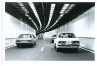
Caption: Sydney Harbour Tunnel IN 1992. HPS boost lighting, fluorescent and interior transition lighting.
Feature image: Sydney M8 tunnel prior to opening. LED interior lighting spaced at 15m intervals. Pavement longitudinally ground concrete. Photo courtesy of Transurban.
Published: 14 March 2023


